How to Calculate Gears

Hello,
As shown in the attached image, I am working with a gear and would like to automatically calculate:
The tooth-to-root distance (the distance from the tooth tip to the bottom of the groove, passing through the gear's geometric center)
My questions are:
Are there any existing algorithms or established methods to automatically measure these gear tooth dimensions?
Are there any tools or libraries that can easily implement this functionality through macros or image processing?
I should note that the macro I've currently written only works for this specific gear image, but what I need is a solution that can be applied to images of any gear.
Attached is the macro I generated and the IQO file used.
Attached is the macro I generated and the IQO file used.
Thank you very much for your assistance!
0
Best Answers
-
Matt—
I've revised the macro, and it can now calculate the required targets.
However, the IQO file used in the process cannot be applied to every gear drawing.Thanks.
—Howard0 -
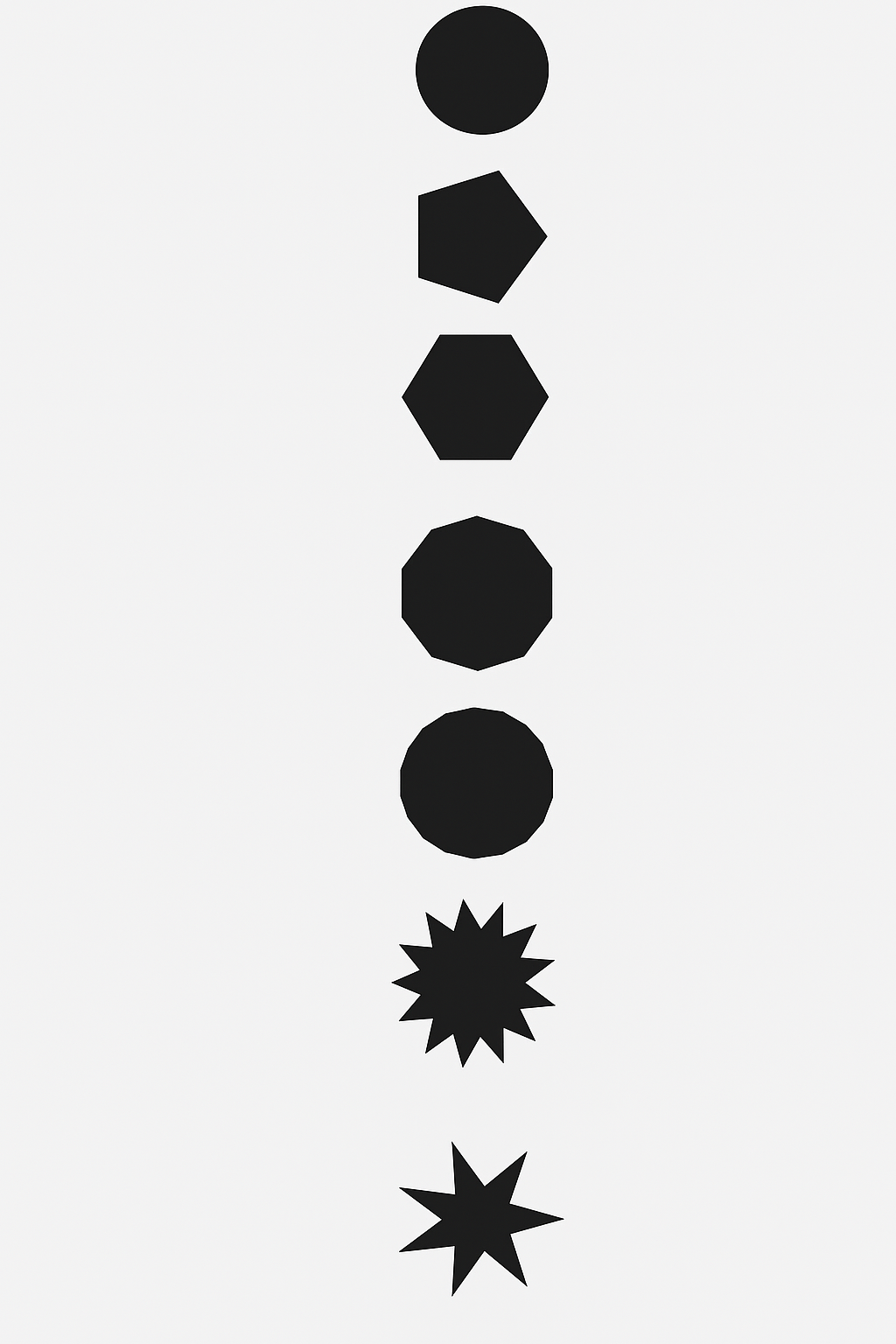
2025-09-24-165922Howard --Here is an EXAMPLE IMAGE that has OBJECTS that are SIMILAR in AREA
 Here is a SCREEN CAPTURE of IMAGE-PRO finding the 7 OBJECTS based on a DARK THRESHOLD
 Using the MEASUREMENT TYPES to include ROUNDNESS as a MEASUREMENT, we can then use EDIT RANGE to set the acceptable ROUNDNESS as shown here.
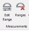
 With a ROUNDNESS FILTER from 1 to 2, and the RANGE OPTION turned on, when the COUNT is run, 5 OBJECTS are found as shown here.
 I have attached the EXAMPLE IMAGE below.I hope this information is helpful.-- Matt
0

Answers
-
2025-09-11-142940Howard --This is an interesting challenge.I have downloaded and reviewed the contents of the file namedGEAR.ZIPthat you posted here on the forum.I would like to run YOUR MACRO on a copy of YOUR IMAGE that does not include the IMAGE-PRO MEASUREMENT LINES. Will you amend this POST to include an ORIGINAL FULL SIZED COPY of one or more ORIGINAL SAMPLE IMAGES please.Thank you.-- MattMatthew M. Batchelor
Alces Imaging and Automation, LLC0 -
-
2025-09-16-115310Howard --Thank you for the THREE IMAGE FILES.The IMAGE FILES that I received are shown here.
 I will try to work on this later TODAY (TUE).Thanks again.-- Matt0
 -
2025-09-18-161432Howard --I attempted to use your GEARS PROJECT on the EXAMPLE IMAGE namedllqwmgwbdylt.tifI received an error as shown in the IMAGE below.I have some ideas on how we might set up the automated analysis that you are looking for but I would like to understand the path that you have followed up to this point.How would you like to proceed?Thanks.-- MattMatthew M. Batchelor
President and Applications Engineer
Alces Imaging and Automation, LLC
2906 Blue Wind Court
Houston, TX 77084
0 -
2025-09-23-134825Howard --Thank you for your message.Do you still have a question on this project that we can help you with?-- Matt0
-
Matt--
I want to know if there is a way to segment based on shape rather than color.
Thank you.
Howard--0 -
2025-09-24-145130Howard --Thank you for your message.Using the TRADITIONAL COUNT TOOL within IMAGE-PRO, the OBJECTS or FEATURES are found via a THRESHOLD of PIXEL GRAY VALUE or PIXEL COLOR VALUE. After those OBJECTS or FEATURES are outlined based on that THRESHOLD, then MEASUREMENT RANGES can be used to FILTER those OBJECTS or FEATURES.I will generate an example image and show you this feature in action ASAP.-- Matt0
-
Matt--
Thank you for your assistance.
--Howard0 -
2025-09-26-140822Howard --ALCES and I are glad to assist IMAGE-PRO USERS.-- Matt0
Categories
- All Categories
- 958 Image-Pro v9 and higher
- 9 Image-Pro FAQs
- 18 Image-Pro Download & Install
- 444 Image-Pro General Discussions
- 487 Image-Pro Automation (Macros, Apps, Reports)
- 20 AutoQuant Deconvolution
- 2 AutoQuant Download & Install
- 18 AutoQuant General Discussions
- 193 Image-Pro Plus v7 and lower
- 3 Image-Pro Plus Download & Install
- 105 Image-Pro Plus General Discussions
- 85 Image-Pro Plus Automation with Macros
- 35 Legacy Products
- 15 Image-Pro Premier 3D General Discussions
- 20 Image-Pro Insight General Discussions