ISSUES WITH RGB to LAB . . .
2022-03-10-180708
All --
I am working with a customer that needs to convert from the RGB COLOR SPACE to the LAB COLOR SPACE.
There are two tools within IP10 that I am looking at to assist.
One is are the REGION MEASUREMENTS of LAB COLOR L, LAB COLOR a, and LAB COLOR b.
Another is
MEASURE RIBBON +
COLOR SECTION +
COLOR MANAGEMENT +
COLOR MEASUREMENT
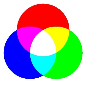
When I use a TEST IMAGE like the one shown here

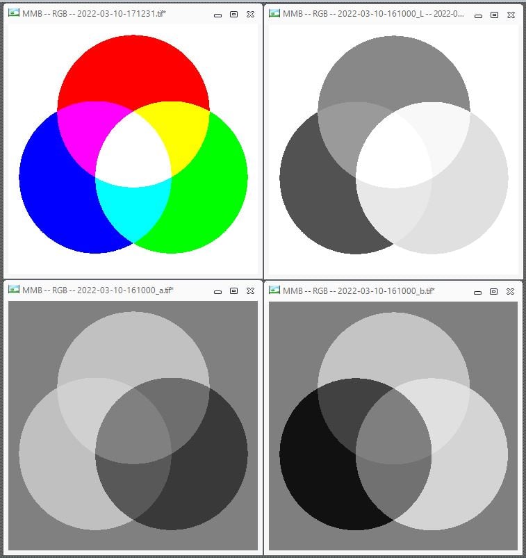
where the CIRCLES are PURE RED, PURE GREEN, and PURE BLUE (PURE being 255) I get different values for L, a, and b when I use the REGION MEASUREMENTS and when I extract images for L, a, and b shown here.

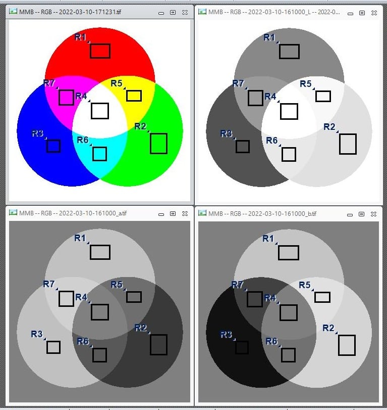
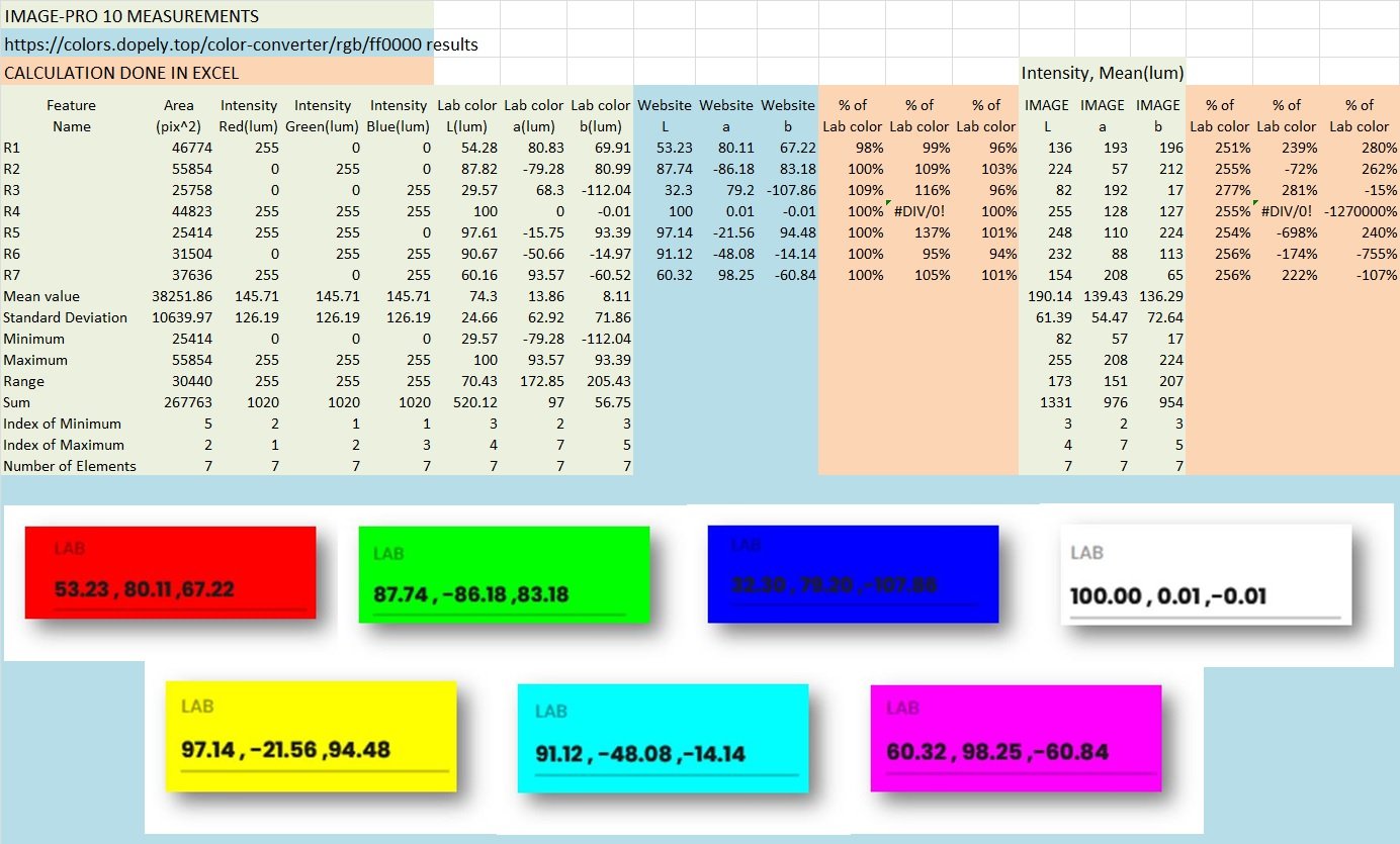
The REGION MEASUREMENTS numbers are pretty close to the Lab numbers generated by two websites that I found but the extracted images are way different. Here are the REGIONS.

This is shown in the EXCEL SPREADSHEET shown below.

The REGION MEASUREMENTS are pretty close to the WEBSITE CONVERSIONS from the RGB VALUES but the IMAGES extracted using the TOOL are much different.
The IP10 HELP FILE regarding the EXTRACT for the L, a, and b does not suggest a reason for this difference.
Will someone here explain this difference please?
A copy of my TEST IMAGE with the IP10 REGIONS stored in it is attached in the ZIP FILE.
Thanks.
-- Matt
0
Best Answer
-
Hi Matt,
If you convert your color image to "Color FPoint" type and then extract L*a*b* channels, the values will be unscaled.
Yuri0
Answers
-
Hi Matt,
Extracted L*a*b* images are converted to the bit depth of the original image, so if your original image is RGB24, the result is converted to Gray8 scaling the intensity values. Every L*a*b* component has different range (https://en.wikipedia.org/wiki/CIELAB_color_space), which is then scaled to 0..255. So, if you are interested in non-scaled L*a*b* values, it's better to use L*a*b* measurements.
Note that the L*a*b* values also depend on illuminant, so if you place measurement regions and check L*a*b* values in the measurement table, the values will change selecting different illuminant (e.g. D50, D65). So, to get proper L*a*b* measurements you must know which illuminant was used when images were acquired.
Yuri0 -
2022-03-11-104814Yuri --Thank you for that information.Is there FEATURE / TOOL / CONFIGURATION in IP10 that will generate an IMAGE that matches the L*a*b* measurements extracted by the REGIONS and displayed in the DATA / MEASUREMENTS TABLE?If not, is there a conversion method that will convert the 0 - 255 8 BIT MONO IMAGES that IP10 generates to FLOATING POINT MONO IMAGES that match the L*a*b* measurements?Thanks again.-- Matt
0 -
2022-03-11-113917Yuri --Thank you for that information.I will try that early this afternoon.Thanks again.-- Matt
0 -
2022-03-11-161234Yuri --I followed your instructions and the RGB to Lab conversion generated the pixel values in the L, a, and b IMAGES that match the L MEASUREMENT, a MEASUREMENT, and b MEASUREMENT from the original 24 BPP RGB IMAGES.Converting the 24 BPP RGB IMAGE to 96 BPP FLOATING RGB IMAGE before doing the EXTRACT CHANNEL TO IMAGE for L, a, and b CHANNELS was the SECRET SAUCE.
Thanks.-- Matt
0 -
2022-03-11-163939Yuri --On a related topic . . .When I do the EXTRACT CHANNEL TO IMAGE for the "b" CHANNEL, some of the PIXEL VALUES are NEGATIVE.This can be seen in the STATISTICS in the IMAGE HISTOGRAM TOOL but the IMAGE HISTOGRAM TOOL in IP10 does not seem to have a CONFIGURATION that will show this graphically.This is shown below.Is there a way to configure the IMAGE HISTOGRAM TOOL to show the range on a FLOATING POINT IMAGE with NEGATIVE VALUES like the "b" IMAGE that generated this HISTOGRAM?Thanks.-- Matt-*-*-*-*-*-*-*-*-*-*-*-*-*-*-*-*-*-*-*-*-*-*-*-*-*-*-*-*-*-*-*-*-*-*-*-*-*-*-*-*-*-*-*-*-*-- HISTOGRAM for ["b" CHANNEL IMAGE] --
 -- HISTOGRAM for ["b" CHANNEL IMAGE + 25] --
0 -
Hi Matt,
Click the Dara Range button on the Adjust tab, display group, and then Reset Range. It will set image range from the data, histogram will also be adjusted.
Yuri0 -
2022-03-14-140141Yuri --Thank you for that guidance.Your instruction to adjustADJUST + DISPLAY + DATA RANGE
 modifies the display of the IMAGE and the HISTOGRAMS displayed by IMAGE HISTOGRAM and ADVANCED DISPLAY.This is shown here.
 Thanks again.-- Matt
0
Categories
- All Categories
- 966 Image-Pro v9 and higher
- 9 Image-Pro FAQs
- 18 Image-Pro Download & Install
- 452 Image-Pro General Discussions
- 487 Image-Pro Automation (Macros, Apps, Reports)
- 20 AutoQuant Deconvolution
- 2 AutoQuant Download & Install
- 18 AutoQuant General Discussions
- 195 Image-Pro Plus v7 and lower
- 3 Image-Pro Plus Download & Install
- 106 Image-Pro Plus General Discussions
- 86 Image-Pro Plus Automation with Macros
- 19 Legacy Products
- 16 Image-Pro Premier 3D General Discussions
- 26 Image-Pro Insight General Discussions

